Author Archives: Ben Mitchell

Strongback issues…

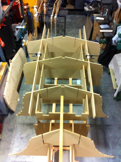
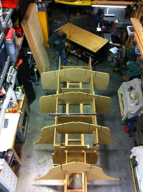
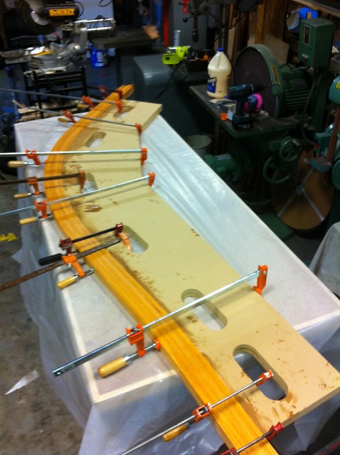
In our last installment, I mentioned we’d gotten a bit ahead of ourselves in the photo I posted.  That’s because you can see, in that photo, both the inboard and outboard stringer in their correct locations, and the plywood transverse frames nested on top of them.  Getting to that point forced us to contend with our first “issue.”

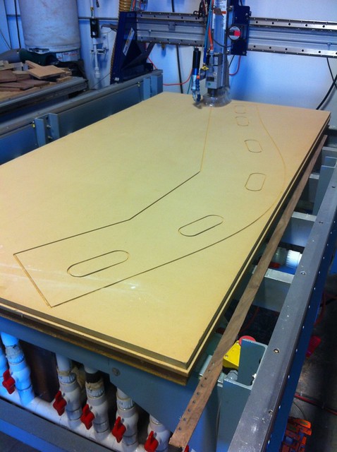
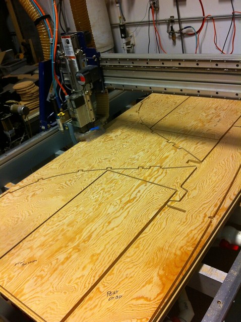
I mentioned before that this is like building a house.  You get plans and build from them.  The plans are not infallible – even the ones fed into the router to produce high precision parts.  A last minute change to the strongback in response to something the other builder had discovered created a minor glitch.

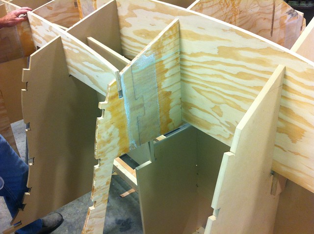
In the image below, you are looking at the port side inboard stringer on the right, which is notched into a frame on the left.  If you look at the top of that intersection, you’ll see that the stringer is not fully “home.”  It needs to slide down an inch and a half before it lines up with the frame.  But if you look at the bottom of the stringer, you’ll see that it’s resting on the strongback already.  No worko.

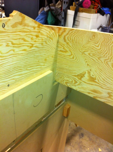
I assumed for a while that I was doing something wrong and kept scratching my head.  Then I called Timm who scratched his head for a while before discovering the problem.  The solution was simple… Cut away enough of the strongback to let it slide down.

As I write this a few weeks later, I’m getting more comfortable assessing what is and is not likely to be a glitch in the plans vs. a glitch in my execution and I’m pestering Timm a little less.  This was the first one though so I got him on the phone before doing anything rash.

-Ben

Real boat parts going together!

In the pictures you saw of the strongback, there were some transverse members that may have looked boat-like to you.  Those, however, are temporary forms made of MDF.  When the finished hull is turned over* they will be cut up and removed.  Chris has now cut out all of the plywood parts and it’s time to start working with them.  The stringers go on first, followed by the frames.  The frames, stringers and strongback are all notched to fit together so it almost feels kit-like at this stage.

Here’s a shot with the stringers installed on the strongback.

Actually, they’re being glued up using the strongback as a mechanism to hold them in place, but you get the idea.  Many of the parts are either too big for a single sheet, or divided into multiple pieces to allow better use of the expensive sheets of plywood (about $100/ea).  Timm very nicely creates locking “puzzle piece” joints that make it really easy to align parts that need to be joined together.  While the stringers were curing, I was also assembling the multi-part frames to install over them.  Here you can see how that works.  Puzzle-piece joint, epoxied together and then reinforced on both sides by a strip of 1808 glass.

This picture gets us a bit ahead of ourselves, however.  More on that in our next installment.

-Ben

*Note: I assume this is self-evident at this point but for those that don’t know, a boat is nearly always built upside down.  The hull is taken to completion – including paint – in this position and then the whole thing is turned over and the interior is finished.

Let’s fill up the shop

This is probably a good time to address one of the handful of questions that’s asked by virtually everyone that learns I’m building a boat:

“Where are you doing this?”

To those that live in some parts of the country this question might sound a bit absurd, but I – dear reader – live in San Francisco.  In San Francisco, deeded parking spaces can sell for $82,000.  Space is highly, highly limited.  And so, this is not an unreasonable question.

For the past year and a half or so I’ve had some shared shop space on the old Alameda Naval Air Station.  We’re right out by where the Mythbusters film (used to film?) the segments of their show that require large expanses of asphalt.  It’s pretty bad ass.

My section is just barely big enough to fit this project.  In truth, it’s not big enough for the project, but it’s big enough for the boat, and the guys in the space across from me are never there.  I end up pushing a lot of my rolling tools and tables into their stall since it makes space to work.

That point established, after the stem the next thing to come off the router was the MDF parts that can be assembled to form the strongback.  For those that don’t know, a strongback is a rigid, stable form upon which a boat is built.  This is kind of a hybrid strongback/jig that positions everything correctly so you can get going more quickly.

Here’s a shot of the strongback after initial assembly.  You can see that beneath it we constructed a ladder-shaped base of 2x4s.  That gave us something to secure everything to, and also allowed us to create a platform that was plumb so there would be less tweaking of the strongback itself to get it level.  Speaking of level, you can also see the level across the strongback frame.  We spent a lot of time trying to get things square and plumb so we’d be building from a good set of reference surfaces.

In this picture you can also see the large stack of 3/4″ Marine Grade A-B Doug Fir ply that will soon be turned into frames and stringers; my dad dusting himself off, and the very small amount of working room that exists on either side of this thing in the shop.  It’s a tight squeeze.

-Ben

A journey of a thousand miles begins with a single step.

That’s Lao-tzu’s, by the way, not mine.

Anyway, you’ve got to start somewhere, and because Chris was a bit backed up and couldn’t cut everything in a single day, I started with laminating the stem since the stem form was the first thing off the router.

The stem is the curved extension of the keel that establishes the shape of the bow of the boat.  Timm supplied a DXF of the shape so we could cut out a form upon which to laminate it.  Here we are cutting that out on the router:

From there, I took a piece of 8/4 S2S V.G. Doug Fir (actual dimension was 1-3/4″ which is the correct width for the stem) and ripped it into 1/4″ strips.  These were then given a coat of virgin epoxy on both sides of each mating surface, and then one side of each received a heavy coat of cabosil-thickened epoxy.  Early on in the project I was using cabosil as my laminating thickener.  I’ve since learned that while cabosil is perfectly fine, you’re marginally better-off using microfibers in this application. But I digress…

Here’s a shot of the layup on the form.

When declamped there was no noticeable springback.  Over the next 24 hours or so it opened up slightly, but only about 1/8 to 3/16″.  If I can keep this whole project within those tolerances I’m going to be a pretty happy first-time boat builder.

-Ben

So is this like… a kit?

No.  It is not a kit.

Some boats are built from kits, but this is not one of them.  The best analogy is to say that building this boat is a lot like building a house.  An architect gives a builder a set of drawings and you go from there.  In this case, we also got some DXF files that could be used to CNC cut the shapes of the frames, primary stringers and a strongback on a CNC router, but that represents a labor savings of about 2% in the grand scheme of things.  What it does do is give you a more precise “foundation” from which to begin.

Here’s a quick shot of the CNC cutting some parts.  I love watching these things go.  And thanks a ton to my friend Chris at VectorPickle who helped with the cutting!

Regardless, the majority of the material is sourced as either marine grade plywood in 4’x8′ sheets, or rough sawn 4/4 or 8/4 V.G. Doug Fir, Western Red Cedar, Teak, or other form of rot-resistant lumber from a lumber yard.  These are then cut or milled to shape on a jointer/planer/tablesaw, and then fit by hand to the boat.  In fact, nearly every one of the pieces that’s cut by the CNC router requires hand fitting by the time it’s all done.  We are truly building a boat.

-Ben

So what is it, exactly, that you’re building…

It’s amazing to me the breadth of initial assumptions people make when you tell them you’re “building a boat.”  Some assume it’s a sail boat, and some that it’s a power boat.  Some assume it will be quite large, and some that it will be tiny.  They are universally shocked when their assumptions are borne false.

What we are building is a small – by my way of thinking – center console fishing boat styled after the traditional Carolina hulls that are more typical of larger sportfishing boats.  This means it has a fair bit of tumblehome aft, transitioning to a very pronounced flare in the bow.  While I’d much prefer an inboard for fishing, the reality is that it’s pretty challenging to shoehorn one into a boat this size, and the project is considerably simpler if an outboard is used, so I’ll be mounting a 115HP Evinrude motor to the transom.

I knew what I wanted before I found the plan set, and spent considerable time searching around for a suitable set of plans.  Ultimately there were a couple of contenders, but I kept coming back to a design by Timm Smith of Smith Marine Design.  The boat is the Kitty Hawk 18, a smaller version of a larger Carolina style hull he’d designed previously.  When I first began discussing the project with him, nobody else had yet attempted to build the boat.  Fortunately by the time I got around to actually starting another builder was already working on it which allows me to benefit a bit from his experience.

The goal of this project is to build something that’s inexpensive to operate, easily trailerable, and suitable for two fisherman, fishing inshore in fair to moderate weather.

I’ve got a bigger boat that’s good for long, offshore trips, bad weather and large groups.  I want something that’s easier to single-hand and easier to move around.

-Ben