Category Archives: Electrical

Odd jobs

We’re at the point with this project where there are lots of little details to sort out.  You bust ass all day feeling like you’re doing stuff, but at the end of the day the boat still looks pretty much the same.  Sigh…

That said, there has been a bunch of stuff accomplished, some of which actually shows when photographed.

First off, I’ve cut the opening for the anchor locker door and applied InterProtect 2000E to the anchor locker, as well as the hidden portions of the hullsides far enough up that we didn’t bother to fill them with balsa.  While I was at it I did the tops of the frames since the teak covers won’t extend very far above the bottom of the inwales.

Untitled

Sorry about the curiously placed plastic crates in that photo. I got them down for a friend that wanted to use one and didn’t have it in me to climb back up and put them away at the end of the day.


I’ve also … finally … finished the work in the transom area.  Here you can see the results.  the hose furthest to port (left) is the outlet from the forward bilge hose.  Moving to starboard, we have the outlet from the aft bilge hose, the outlet from the bait tank, and finally the outlet from the sump pump.  To keep things from moving around too much I tied the port side hoses together with clamps.  This made a big difference.  On the starboard side, I actually added a block that I could attach a clamp to for the sump outlet.  I did this because the sump hose is 1″, but the throughhulls I found didn’t come in 1″, only 1 1/8″.  I had to adapt using barb fittings and a short length of 1 1/8″ hose, which means there’s a lot going on there.  I wanted it well supported.*

Untitled

If you look at the starboard side under the throughhull plumbing you’ll see some wiring and hoses that disappear into the corner. That’s the fuel line, the oil line, and the oil level sender cable. They route up through the fillet-chase on the outside of the motorwell. There’s also a piece of leechline tied off to the hose mount. That’s a pull cord in case I ever need to get anything else through that chase.

Having now finally finished everything I could think of in the transom area I boldly decided to do something that looked vaguely like progress and I bonded in the motorwell bottom. Here it is with a bunch of steel drops and some scraps of granite holding it down while the epoxy cures. Also to the right in this photo you can see the hoses and wires that are run up the chase:

Untitled

Further progress on the hullsides is somewhat impeded by the varnishing process for the frame covers. I’m still deciding if I want to prime before or after putting those on. In the meantime, the kitchen in my apartment is masked off to try to keep the fumes down while I varnish the covers here. It was just too cold in the shop.

While the varnish is going on – it’s going to take quite a while – I can now begin work on the gunwales and the inner part of the motorwell. I may also take a crack at mocking up the console to make sure I like what I’ve designed on paper.  Would be good to get that in progress sooner than later.

-Ben
 

*Note:  1 1/8″ barb fittings in bronze, brass or marelon are scarce as hen’s teeth.  Originally I used a plastic adapter that’s purpose built for going from 1″ to 1 1/8″, but I got nervous about using plastic since this would be a bear to change later.  (Doable, but annoying.)  I bought a 1-1/4″ threaded barb fitting in brass and turned the threaded end down to a barb I could get into the 1″ hose, and the 1 1/4″ end down to a 1 1/8″ barb and used that instead.  I feel better now.

Yes, yes. We’re still at it…

In candor, I didn’t think many people bothered reading these updates. Seems I was wrong. Go a month without posting anything and people come out of the woodwork wondering if you’re still alive.

I assure you, we are.

And we’ve been busy.

In our last installment, you saw the beginnings of the scupper/sump system. Once the plywood “box” was built, it was bonded and glassed to the port aft corner of the bilge, and holes were bored to enable the routing of two pieces of fiberglass pipe from the collector cups to the sump. At present, there’s no lid on the box, but ultimately one will be fitted, and it will include a vent so that the system doesn’t air lock.

Untitled

Next, we went to work on the access hatch that permits servicing the sump, and that mounts the float switch. It also has cable glands to permit the wiring to the switch to exit the box. You’ll recall that I started with a SeaBuilt 6″ access plate. I took this to the Bridgeport and, using the DRO to get it all lined up nicely, drilled six holes. Two permit mounting the switch, and the other four are for the cable glands. The glands require a 1/4″ NPT threaded hole, so I first drilled pilot holes, and then finished with the appropriate size drill for a 1/4″ NPT tap.

Untitled
Then I tapped the holes using a manual tapping tool, but on the Bridgeport to provide a secure clamping surface.

Untitled

The glands are IP68 rated so they’ll be fine if the box fills up for an extended period of time.

Once this was done, it was time to start preparing to lay down the boat’s deck. Before that happens, we needed to:

  • Run a rigging chase from the console area to the machinery space.
  • Foam the floatation areas
  • Prep and paint the “man accessible” areas of the bilge
  • Install the pumps and plumbing
  • Prepare the deck panels by installing the gutters and painting the undersides

We kinda blew through this without stopping to take many pictures, but here’s a good shot showing the aft areas ready for the deck to be installed. If you look closely, you can see that access plate we machined installed in the (still topless) sump. There’s a bilge pump aft, a washdown pump on the starboard side, a bait pump in front of that, and on the port side there’s an oil reservoir for the motor forward, with a macerator pump connected to the sump aft of it. Beneath the macerator is a 1kW throughhull transducer for the sonar.
Untitled
Up front, I installed a drain in the bottom of the anchor locker to allow any moisture that accumulates there to run back through the floatation area to the bilge.
Untitled

Untitled

Next up, for each of the hatches we had to lay up the gutter. Each gutter consists of three pieces. Here’s the forward compartment’s gutter, clamped up and curing
Untitled

Once they were cured, we bonded them to the underside of the deck panels and, because I’m ridiculous, I then painted the “visible” parts white to match the sides and bottoms of the lockers.
Untitled

Then we put in the deck panels. At least we did the lower ones. The forward ones will go in tomorrow. Unfortunately I didn’t take a picture of this process, but it wasn’t very complicated. I did decide to drive a bunch of bronze screws in to augment the epoxy bond. These are the first fasteners intentionally left in the boat.

Once the deck was in, we turned our attention to filling the voids between the side stringers. By design, these are left as they are and just sanded and painted. We can do better.

I bought some 3/4″, scored, scrim-backed end-grain balsa panels and we’re bonding them into the gaps. This will then be covered with glass. This is purely an aesthetic endeavor, but it will have the effect of turning the hullsides into a 1.25″ thick cored structure, which will be absurdly rigid and strong. To get the balsa panels properly bonded to the hull we’ve opted to vacuum bag them in place. There’s no way to clamp them without doing this.

Here you can see, on the left, a section that’s got the balsa installed. On the right is a section being bagged.

Untitled

Once we got comfortable doing this, we started doing multiple panels simultaneously.
Untitled
We had to order more of the Stretchlon bagging material from Fiberglass Supply, so we’re currently stuck at the halfway mark on putting in the balsa. Today we filled some of the voids between the frames and the balsa we’ve already put in, and then got to work on the motorwell. Timm’s design calls for the motorwell having either a square corner, or a 5″, 45-degree miter. Both options leave “sharp corners.” We can do better. I CNC’d some quarter-circles with a 5″ radius and cut a bunch of strips of plywood with 3.5-degree angles on each side. Twelve strips of appropriate width can be bonded together to create a 90 degree arc. Here’s the first corner being laid up.
Untitled

Here it is bonded to the face panel for the motorwell. Note that the “top” part will be trimmed once it’s all assembled.
Untitled

I’m not sure I’m wild about the idea of the top edge of this thing being only 3/4″ thick. I think it’ll look “flimsy” relative to the thickness of the transom. Once I see how it comes together, I’ll probably take 1″ balsa and bond it to the outside before glassing everything. That’ll make it 1.75″ thick, which is more meaty.

Oh. One other detail. We need a rigging chase to get the fuel and oil lines from the aft part of the bilge up to the underside of the starboard gunnel where they’ll join the steering and electrical connections and be routed to the motor from the side of the motorwell. To do this, I’m creating a hollow “fillet” between the motorwell and the transom. I laid up two layers of 1808 tape over a piece of 6″ diameter PVC pipe, covered it with plastic and wrapped it in masking tape to compress it. Once it’s cured, I’ll cut 1/4 sections of it to create big fillets for each side.
Untitled
Okay. You’re more or less up to date at this point. I’ll try to be more diligent about updating things. It’s been a grab-bag of little projects so nothing seems worth writing about, but as I type this up it’s clear a lot has happened since I last checked in.

-Ben

Hull details

We’re working inside the hull, now.  Some of it is straightforward and laborious.  Some requires lots of mulling and tinkering, but very little actual effort.  It’s a nice balance.  But it’s taking too long.

The first thing we had to do was sand the rough bits of epoxy and such off the inside.  Not too bad.  Then we had to fillet the stringers and frames to the hull.  This needs to be done for all the frames and stringers – above and below the deck – but we decided to start by just doing the below decks areas under the theory that it’ll be easier to fillet the upper parts once the deck is in and we’re not tripping on framing trying to move around.

This took a day and a half or so to do, and it takes a startling amount of epoxy and filler.  Some of the fillets are best made quite large to distribute the load, and the majority of them need to be done carefully so they’re smooth when you come back to tape over them with glass.  Invariably, they’re not perfectly smooth, however, and so there was a day of sanding and “tuning” that had to be done after the fillets went in before we could do the taping.

The tape had to completely line all of the seams of the compartments framed by the stringers and hull, which required just under 100 yards of tape and over 4 gallons of resin.  Timm specified 1808 tape which is (a) hard to find, and (b) sucks up a huge amount of resin.  I think it’s probably overkill, but I’d rather overbuild than underbuild when it comes to things that affect structural integrity of the hull.  1708 tape can be had anywhere, but 1808 I had to order from an eBay seller.  Timm was pretty adamant that I should use the 0-90 1808 over the 45-45 1708…

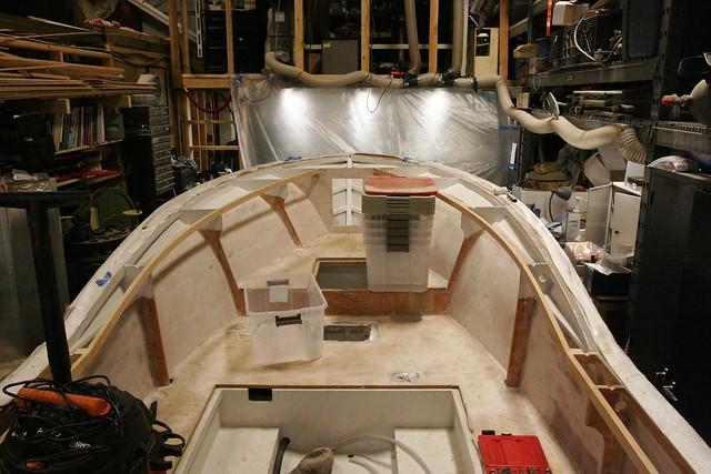
I wasn’t very good about taking photos as I went along, but here are some good shots.

Untitled

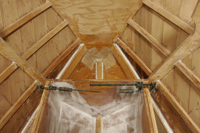
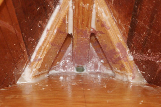
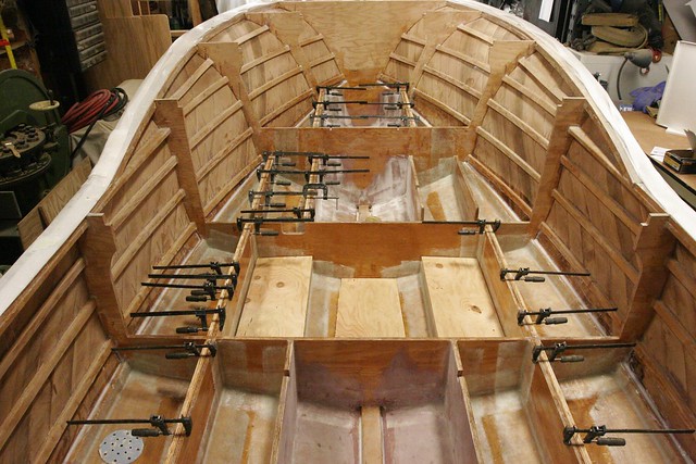
In this one, you can see the filleting around the chine logs and keel, and you can see the tape in that foremost compartment.  The tape in the main compartment is covered with fairing compound.  I decided to fair smooth all the man-accessible compartments since invariably I’ll be crawling around in them someday and I don’t want to get fiberglass splinters.

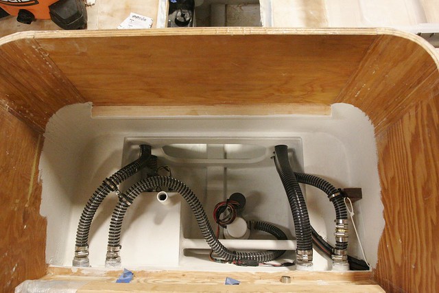
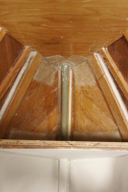
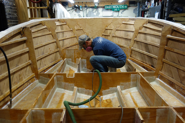
Here you can more fully see the taping of the frames and stringers.

DSC04951
As this was all going on, I was contemplating the question of scupper drains for the deck.  Timm’s design is for a self bailing hull with scupper slots cut in the transom at deck level.  The problem is that this is very close to the waterline.  After some reading on the web which suggested that scuppers are one of the leading causes of small boat sinking, and also some discussion with Timm, I decided to abandon the self bailing feature and configure things so water that comes aboard gets pumped out.

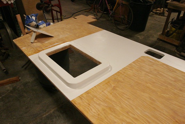
This doesn’t mean I want it to end up in the bilge.  I’m going to work pretty hard to keep the bilge of this boat dry by putting hatch seals in the deck and such, so I decided to create a sump under the motorwell just forward of the transom, and set two scupper drains in the aft corners of the deck that drain to the sump.  The sump will have a float switch inside it – accessible via an inspection port so it can be replaced when it fails – and will be connected to a macerator pump that will purge the sump when it fills.  This is all very complicated to implement, but it’s actually a pretty simple system and should work well.

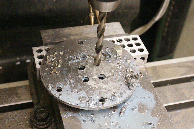
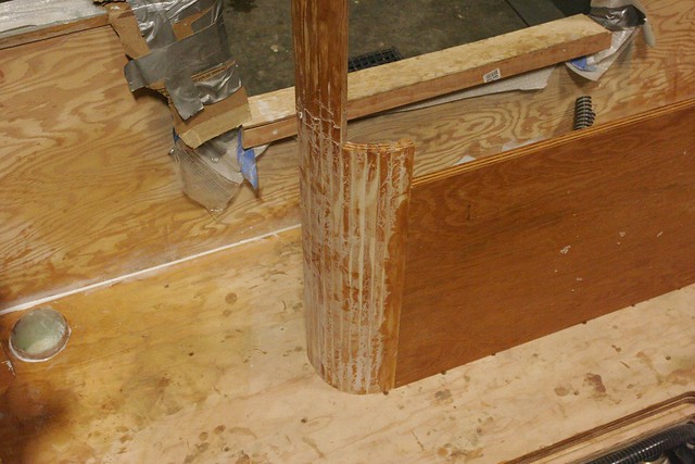
To make the drains for the corners of the deck, I cast glass over a pair of quart mixing cups to create 4″ diameter fiberglass cups.

Untitled

Untitled

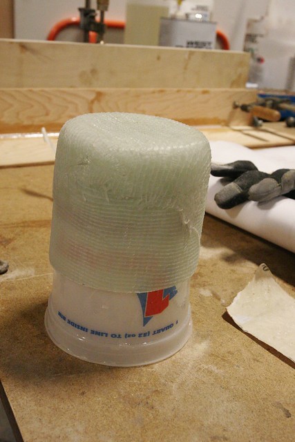
These will sit about here:
Untitled

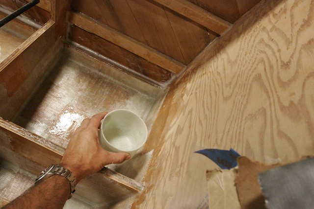
Because these compartments will be filled with foam, the plumbing connecting the cups to the sump will not be serviceable. It needs to last forever. I ordered some 1″ ID pultruded fiberglass pipe from McMaster-Carr so I can create a completely fiberglassed system with no joints.

Just before we ran the cut files for the deck, I added 4″ cutouts for these cups. The interesting trick will be to get the cups and pipe all epoxied together in just the right position so the cups line up just under the holes in the deck. That’s a “to be done” project.

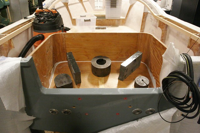
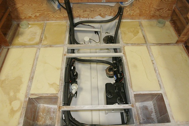
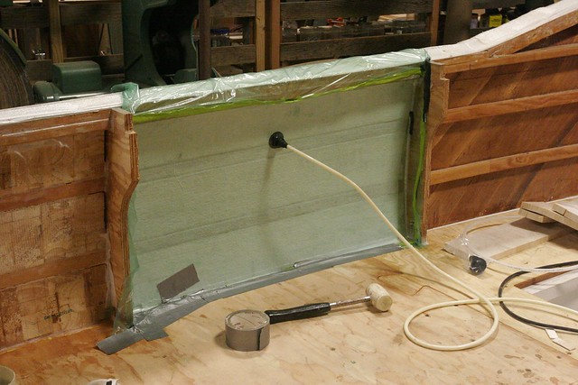
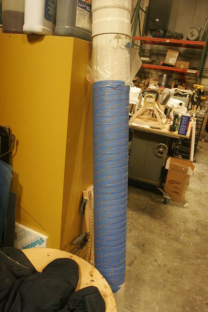
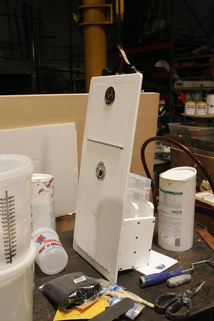
Here’s the sump box in progress. You can see the lower hole which will get a bulkhead hose fitting to connect to the pump. The upper hole with the bolt circle around it is for the SeaBuilt 6″ stainless steel inspection port. The switch will be mounted to the back side of the port cover, and the wires will route through the cover using IP68 rated cable glands. That way, when the cover is removed all the wiring and the switch comes with it so it’s easy to service.

Untitled

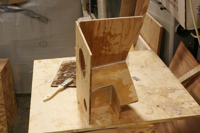
You can see looking at this that I’ve made it as complicated as I possibly can ;-)  The interior framing is intended to minimize the amount of water that can collect below the level of the pump’s pickup, so there will be as little standing water left as possible when the switch shuts off.  If it’s not clear, this gets mounted in the corner formed by the inboard port stringer and the transom, which provide the other two “walls” of the sump.  Once it’s all together and I confirm it’s watertight, I’ll glass a lid onto it.

I ordered a bunch of Molex MX150 connectors. These are rated to 20A and are IP68 rated. This will make it easy to connect and disconnect pumps and other parts without tools, and the connections will be watertight.  The crimper pliers appear to be unique to the MX150 pins, so I had to order those too.  $120.  Awesome.

The mechanical space – the aft most storage area just in front of the motorwell – will have all the pumps, throughhulls and other mechanical bits. This includes:

  • Macerator pump for deck sump
  • 1500GPH Bilge pump
  • Livewell pump
  • Washdown pump
  • Fuel filter
  • Oil reservoir
  • Sonar transducer

The livewell pump and washdown pump share a single 3/4″ throughull with a seacock.  The only other hull penetration below the waterline is the transducer.  I’m opting not to install a drain plug.  The pumps should be sufficient, and we don’t get freezing weather around here so it’s not critical that the hull be completely, totally devoid of water.

This is a lot of stuff to screw to the wall of the mechanical space and my experience in the past has been that because these items fail from time to time and need to be replaced, the screws tend to loosen and the wood behind them gets damp. I decided to order some brass E-Z Lok threaded inserts.  I’ll drill holes in the appropriate locations, screw them in once to create the threads, then take them out and soak the holes with epoxy which will cure before I put them back in with a dab of 4200 sealant.  That’ll make them more removable later.  Once these are in place the pumps and other machinery will thread into them with machine screws instead of wood screws.  The machine screws can go in and out as often as needed without damaging the wood. I was a little hesitant about using the brass inserts since I’ll probably use stainless screws and, especially in salt water environments, you need to worry about galvanic corrosion. Brass and stainless are pretty compatible though, and I can always use brass machine screws if I want to be really safe.

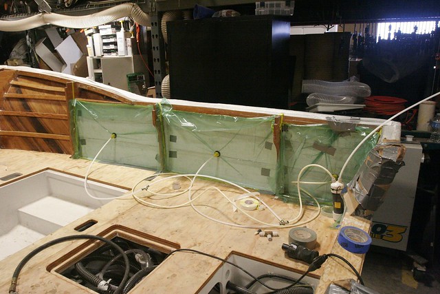
Other developments include the installation of the first half of the frame/stringer doublers which create a greater bonding surface for the deck.  You can see those, as well as the to-be-sealed and installed tank supports in this photo:
Untitled

For most of these doublers I’m using scrap 3/4″ plywood, but the areas around the fuel tank are supposed to be solid wood because the access hatch over the tank is held down with screws not epoxy, and screws don’t hold well in the edge grain of plywood. Unfortunately there was a foul-up with the cut files and so a void that was supposed to make room for a special piece of solid wood for this purpose was omitted. I have to decide how to handle that situation, still.

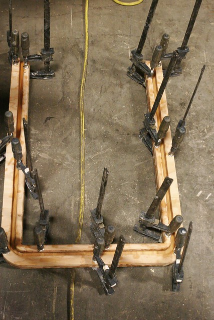
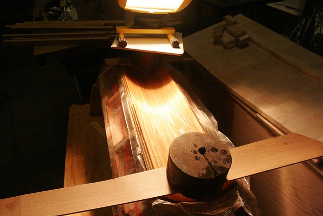
I’m also continuing to work on the CNC-cut storage units for the leaning post.  Here’s the first of them.  It’s nearly done, but there’s still work to do. There’s always work to do…

Untitled

Okay, so from here we need to get the plumbing glassed in for the deck drains, glass in and seal the sump, do the final epoxy sealing of the insides of the hull.  Install the last of the doublers, and foam the floatation compartments.  Then I’ll paint the storage/mechanical spaces with white-tinted epoxy, install the machinery, and move onto the decking.  Yee haw…


-Ben