
I’m tired of apologizing for long delays, but I find myself once again in that position. Sigh…
In any event, the lack of updates does not indicate a lack of progress! We are very nearly done with the boat.
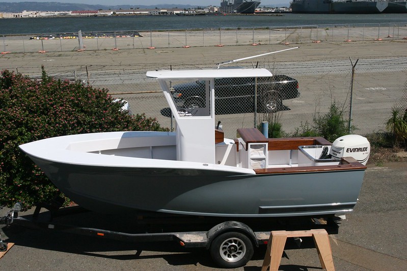
The gunnels are faired and painted with gloss white. Still haven’t done the non-skid, but that’ll be one of the last steps.

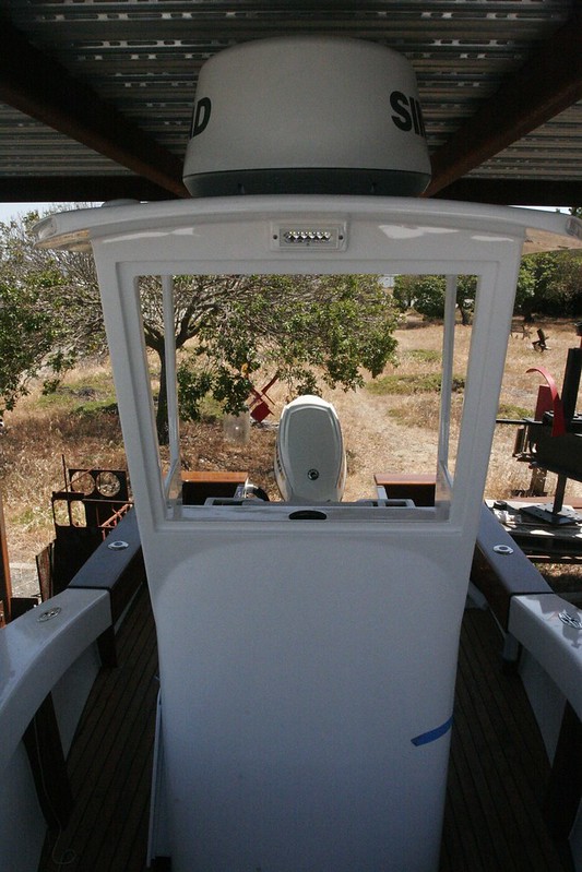
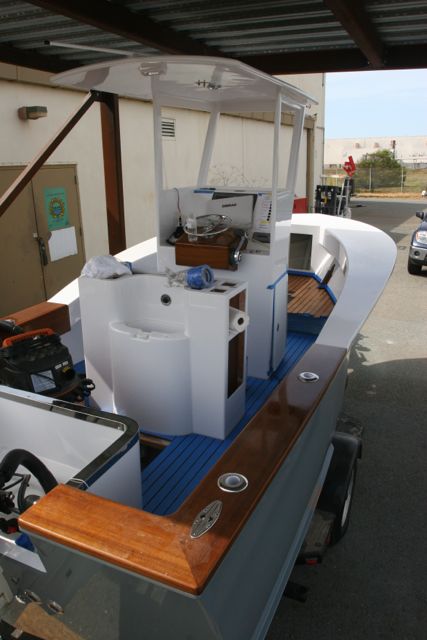
The console and leaning post went in pretty easily. Good things come to those with forklifts.

This is what she looks like with those items sitting in place. When this photo was taken the seat board wasn’t attached yet and the furniture wasn’t bolted down, but it’s a good visual.
After that, we (okay, this is more of an “I”… my dad’s not much on electrical) moved on to the wiring. I believe I’ve mentioned before that I designed some custom circuit boards to control the awesome little buttons I found. Here’s one of them all soldered up.
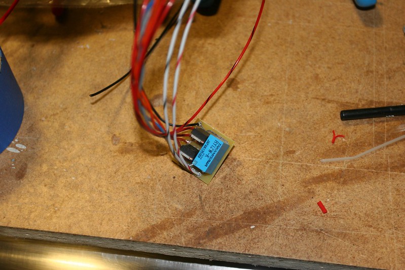
There are actually two designs – one for the thirteen circuits that have a simple on/off and one for the five circuits that have dimmers. But the basics are the same.
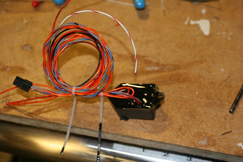
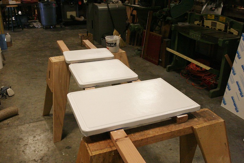
Each one of the boards gets potted in resin to seal it and protect from environmental exposure. You can also see the four-contact mini-connector that connects the button to the box. The other leads are all done with standard quick disconnects that will be added later.
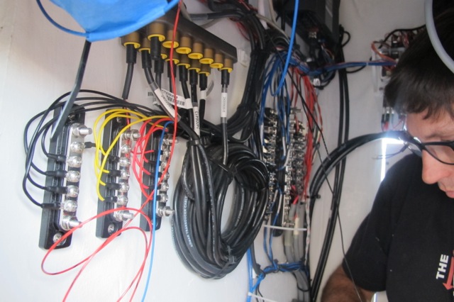
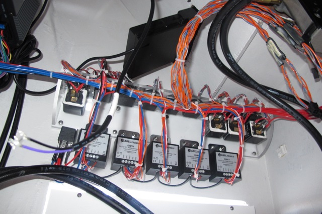
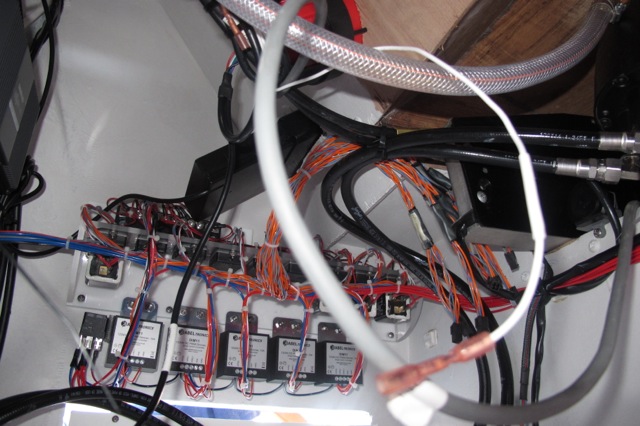
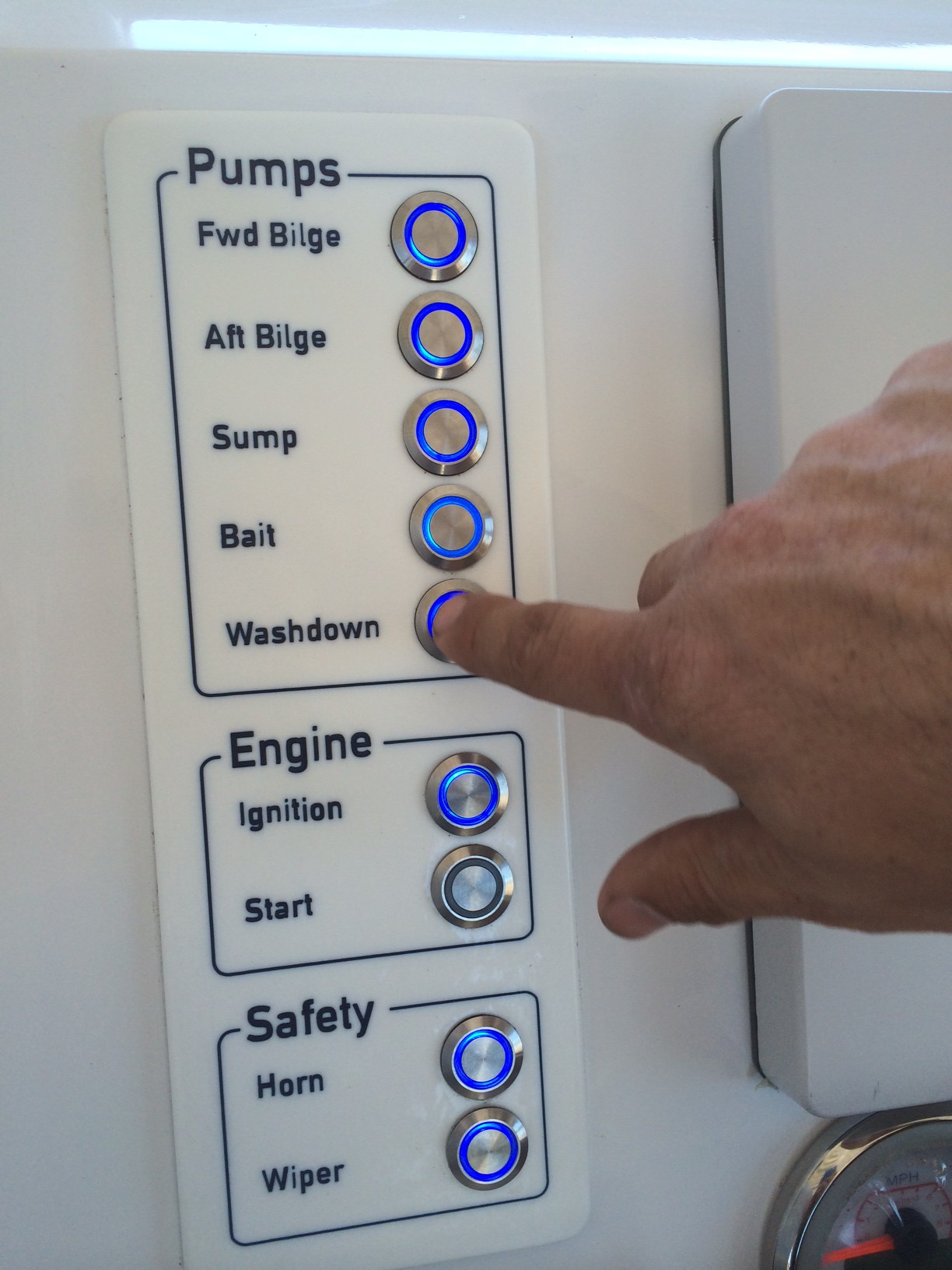
Each one of the switch panels has 9 buttons on it, and so I CNC’d two mounting frames to hold the supporting control-box / relay / dimmer assemblies.
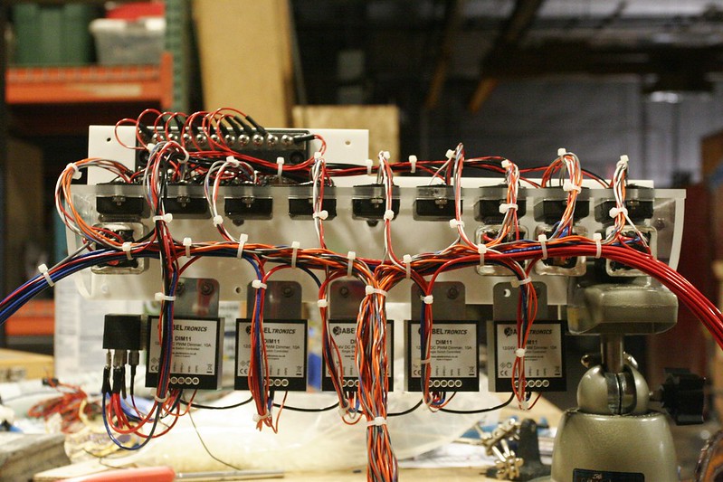
This one supports the panel for lighting. You can see the row of control boxes at the top. The leftmost box and the three at the right end each have a DNI0127 relay attached beneath them with industrial velcro. These are “on-off” circuits. The other five have no relays, but instead connect to the five ABELtronics DIM11 relays you can see at the bottom of the frame. These dimmers turn the circuit on or off with a momentary button press, and if you hold the button down it cycles through the range of dimming. For things like the deck flood lights I wanted to be able to dim them down because in the early morning you might want a little light, but not to be overwhelmed. The observant viewer will note that the leftmost dimmer has a relay attached to it as well. That’s the “Instrument” dimmer. When it’s “on” it turns on (and dims) the backlights for the switch panels, plus the compass. It also dims the LED rings on the buttons so everything looks consistent. When it’s “off” the compass and switchplate lights go off, but we still need to illuminate the buttons, so that SPDT relay switches the buttons back and forth between the dimmed output and a 12V+ source so there’s always current to the button LEDs regardless of the state of the Instrument lights switch.
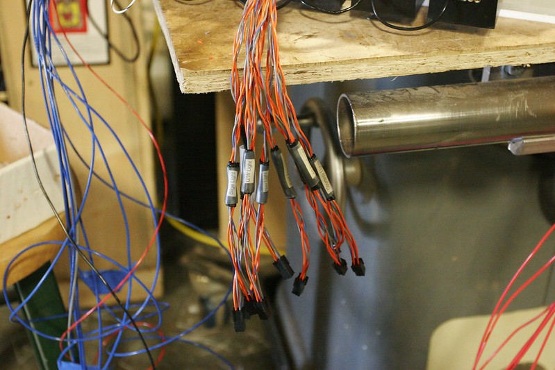
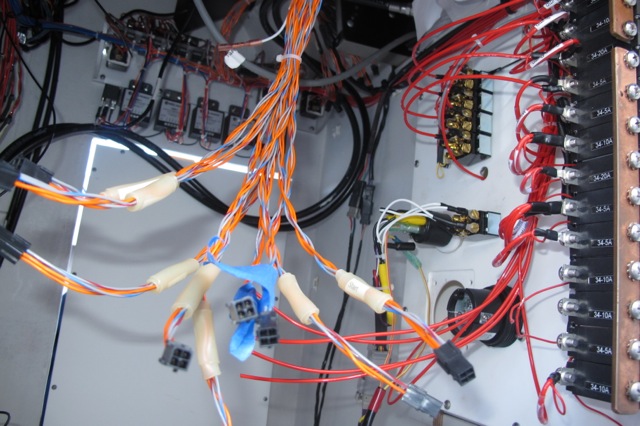
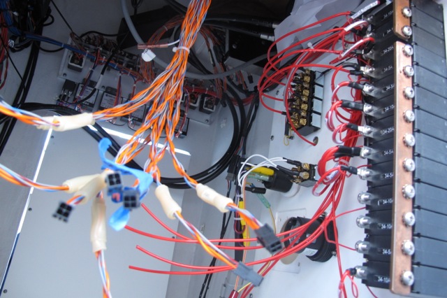
Here’s a shot of the pigtails for connecting the control harness to the buttons. Each pigtail is appropriately labeled since it’d be impossible to figure out which was which once they were all zip-tied into a harness. There were 144 miniature pins that had to be crimped to 20ga wire to for these. Ugh.
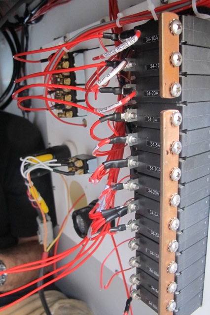
The complete assemblies (which thankfully could be built from the comfort of a nice workshop bench) were mounted in the console as single units. The (hundreds) of wires that then needed to be connected to integrate them to the boat were all fit and cut to the correct length, crimped, soldered and heat shrunk in the (very, very confined space of the) console.
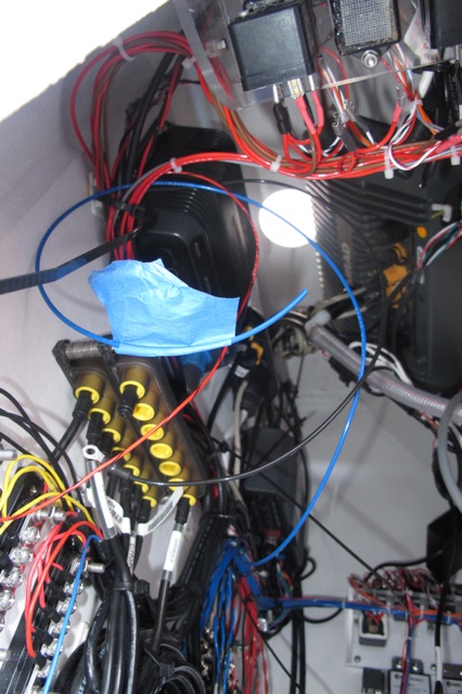
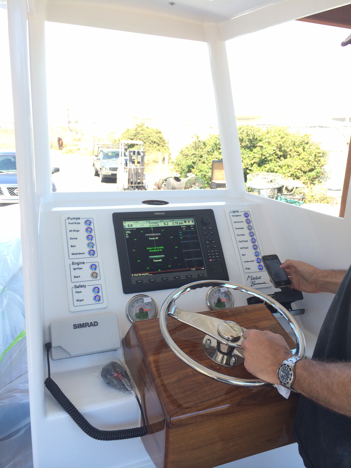
At about this same point in the process the electronics suite, the battery charger, and a bunch of other stuff went into the console. The lights and other bits all got mounted as well:
There’s a lot of wire in this boat. On the topic of wire, I used really nice wire. It’s Milspec aviation wire with Tefzel insulation. The insulation is more abrasion resistant and thinner than standard marine wire. And rather a lot more expensive. Sigh…
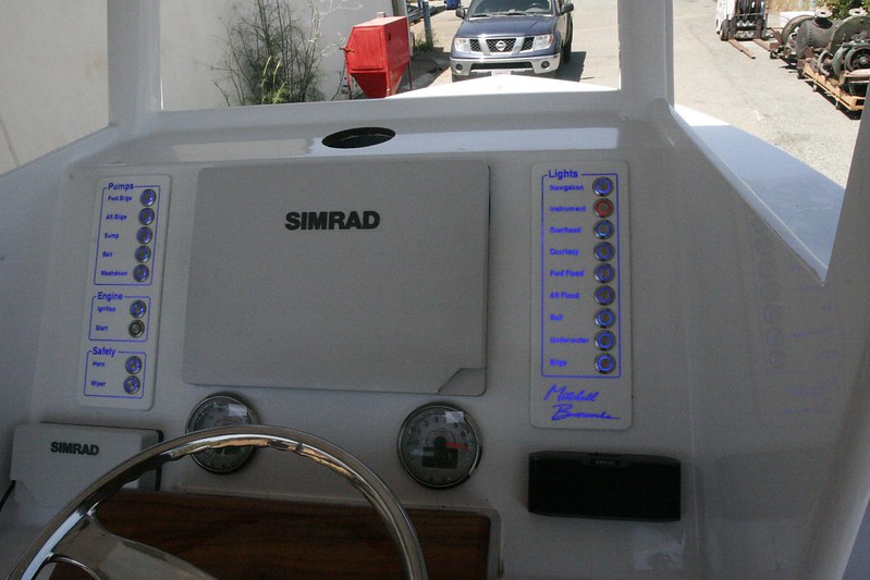
Once it’s all together, the dash is very nice and clean, belying the complexity beneath:
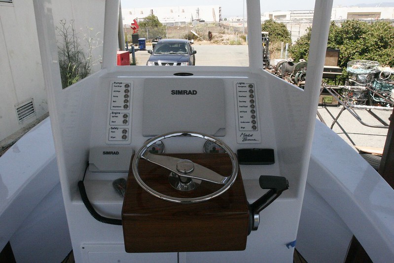
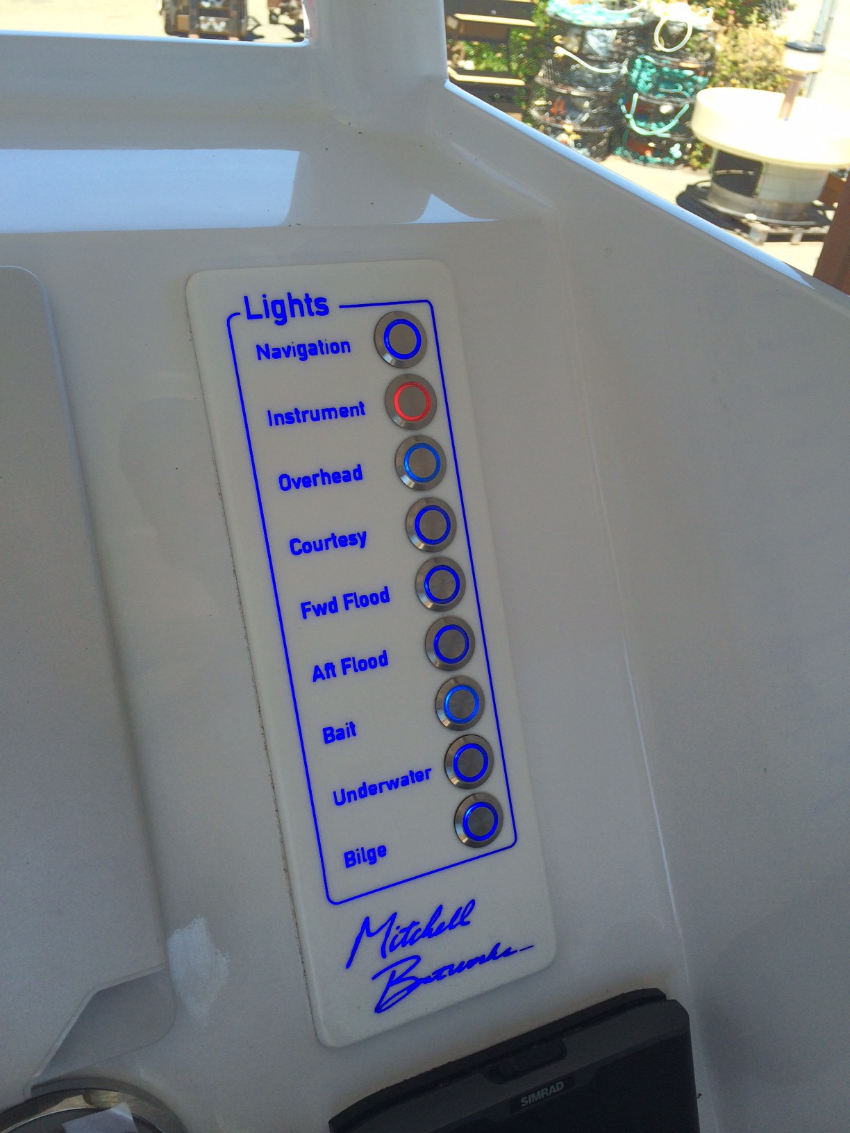
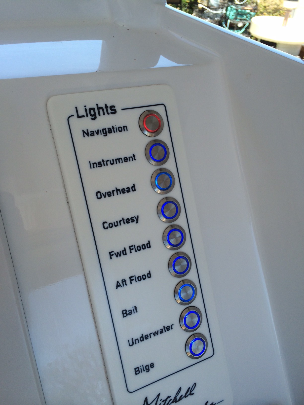
And it looks pretty cool when the panel backlights are on:
The decking then went in.
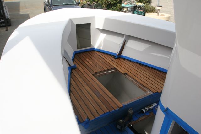
The hatch covers were teaked on top, and then I cut grooves in the bottoms for hatch seal.
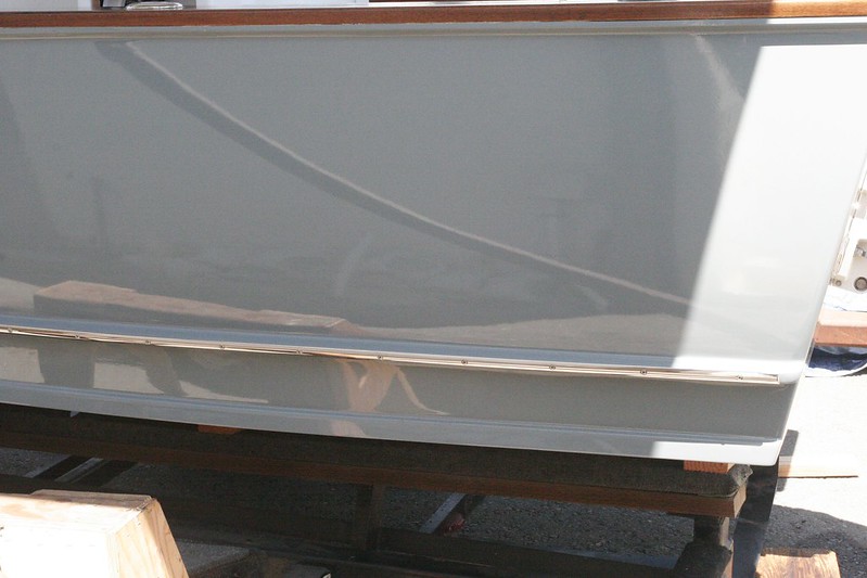
And I repaired the quarter guard from it’s run-in with the pole, and installed the stainless rub strips onto it.
Also installed the windows, though I have no photos of that process.
At that point, we took a one-month break from progress while the boat got a fancy new aluminum trailer made at Pacific Trailers in Chino. I just got her back – photos to come – and the final sprint has started.
On Thursday she went to Outboard Motor Shop in Oakland where they fired the motor for the first time. That generally went well, but did reveal a pair of problems I need to address. The tach isn’t working and the Ignition button doesn’t shut the motor off. I’ve figured out how to fix the Ignition button issue (two more relays and a diode) but the tach I need to look into.
And then the list looks like this. I realize most of these items are cryptic and poorly explained but the point of the list is more to show how SHORT it is. We’re talking days here, people. Seriously. The boat is nearly done:
Rub rail install
Clean up windows
Clean bilges
Paint hatch lips
Paint bilges
Deck sanding
Finish fabricating access door
Install battery trays
Mount access door
Futz with bow eye
Window UV Paint
Finish fabricating leaning post storage
Install leaning post storage
Hatch cover seals
Install hatch covers
Install hatch latches
Install drain grates
Caulk stainless motorwell cap
Caulk seam between coverboards and gunnels
Non-skid
CF numbers
HIN on hull
Prop selection