The stringer slog

Installing side stringers is a patience-trying endeavor.  There are a lot of them, and due to the nature of this boat, each one takes a fair bit of time to set up and clamp.  Then you wait overnight and do it all over again.  In total, there are 10 stringers to put in, and a lot of them “whole day” projects, not because it takes all day, but because of the number of clamps required and the delicate nature of the operation.  Once they’re on there, I’m loathe to bang around on the hull lest I unseat something.  So you end up knocking off early those days, which feels pretty inefficient.

With the exception of the very top stringer (which is the bottom one on an inverted hull) they go in pretty easily.  I won’t bother you with long-winded descriptions, but here are some photos to give you a sense for what’s involved.

My father is fond of the adage “Patience is a virtue.”  I’m ready to be done with stringers, but this is a critical step and can’t be rushed.  These set the foundation for the hull skin, and it’s a lot easier to get it right now than to fix it later during the fairing process.

-Ben

Chine Logs

I’ll start with a nod to my father’s suggestion, buried somewhere down in the comments, that I be a bit better about explaining arcane boat building terminology when I employ it.  A boat such as this one has “hard chines.”  The chine is the intersection between the sides of the boat, and the bottom of the boat.  In the forward (front) areas this is a barely perceptible transition, but as we move aft (back) it quickly becomes a sharp angle.  That sharp angle is what’s implied by the term “hard chine.”

When we plank (skin) the hull we will use one set of planks for the sides and one for the bottom.  These intersect at the chine, and they need a fairly stout piece of framing behind the intersection to support them and bind them together.  These are known – presumably for reasons dating back to when they were comprised of actual logs of an appropriate shape – as “chine logs.”

The chine log on the KH18 starts at the transom and runs all the way forward, ultimately intersecting with the stem.  It’s for this reason that the keel and stem were just installed in the boat – I had to mate the chine logs to the stem, so it had to be there first.

Step 1: Shape the stem.  When the stem was installed it was  a curved block of wood.  The bow of a boat is not, however, a a flat chunk of wood.  It’s nicely pointed to break water.  To achieve that angle, I took a block plane and a spokeshave and trimmed off the edges until the desired angle was achieved.  Here’s an “in progress” shot of that:

Once the angle was right, I had to notch out pockets for the chine logs to sit in.  This was done with a pull saw and a very sharp chisel.  Here you can see the starboard side pocket, with the corresponding notches in the plywood frames in the background:

The chine logs are 1″ x 3″ total, comprised of two strips of 1/2″ x 3″.  Here’s the starboard one after being laid on and clamped in position:


And here’s the port side, installed after the starboard had fully cured, the forward end trimmed and a port side notch cut.


Later, these will have to be shaped with a block plane to achieve the correct angle and size, but more on that later.

I should note at this point that for efficient use of material, in many cases I’m creating composite members not just for thickness, but also for length.  The chine logs and most of the stringers are comprised of sections.  Here’s a shot of one of the joints:

This has only a minor effect on the strength of the member.  The butt joint between the two sides is completely filled with thickened epoxy, which is as strong or stronger than the wood surrounding it.

Keel laying

Traditionally, I guess the first thing you did when you built a boat was to lay the keel.  Or maybe that’s just with ships too big to be built upside down.  I don’t know, but I do know that I did a lot of work before I got to the point it was time to assemble the keel.  But that time has come!

The first step is to laminate the aft portion of the keel.  This is done in place, on the frames, so that it fits the contours perfectly.  But you have to be careful not to actually bond it to the frames because you have to be able to remove it after it’s bonded so you can shape it to mate with the stem.

Here’s the keel being laid up.  If you look closely you can see that there’s a piece of plastic between the keel and the frames at each station.

Here’s a shot from the aft end of the keel…

Don’t stress about those cracks in the bottom member.  The keel overhangs the transom by a fair bit at this point and the cracks only run an inch or two forward.  Besides, that piece is now bonded to the one above it, which will hold the cracks together.  This is one of the many reasons a composite board is stronger than a single board of the same dimensions.

Once the keel cured, it came off the boat and got fitted up with the stem.  That required that the forward end of the keel be tapered in on both sides, and that a notch be cut from the stem to create a longer joint.  These were then clamped and bonded in place on the boat.  Here’s a shot of the whole kit ‘n’ kaboodle being clamped on the boat.  The Stem is the part on the left, including the protrusion that sticks aft of the MDF frame by a bit before tapering down.  The keel is the lighter-colored piece that’s resting on top of the protruding portion of the stem.

Those two small pieces of plywood on the tops of the two parts were nailed there temporarily to give a purchase point for applying clamping pressure to pull the two together.  then it was clamped in a couple of other places vertically along the 10-or-so inch long joint.

The keel is 3″ wide and 1-1/2″ tall.  The stem is 1-1/2″ wide and 3″ tall.  That’s why the keel needed to be tapered in the forward end to fit.  That was an amusing operation for which I don’t have a photo.  Basically we cut wide of the mark on the bandsaw and then snuck up on the line on each side using a 24″ pedestal disc sander.

The keel is done!  Long live the keel!

-Ben

Longitude!

Or, more accurately, “longitudinal.”  We’ve got the plywood framing all in place at this point and it’s time to start laying the lengthwise timbers.

“Longitude” as a posting title, however, gives me a chance to plug an exceptional book of the same title by Dava Sobel. You’ll never take your watch for granted again after you understand the scope of the human effort that went into developing a method for keeping time that could remain accurate while aboard a vessel rocking on the ocean.  Pendulums don’t like that much…

But I digress.

Whereas thus far, with the exception of the stem, we’ve been working exclusively with sheet lumber – plywood and MDF – we’re about to start working with more traditional boatbuilding materials.  We’ll be constructing longitudinal members by laminating together strips of V.G. Doug Fir as necessary to make the bends required by the design.  We’re starting with the bottom-most side stringers, which you can see clamped up in the following photo:

The required final dimension for these stringers is 3/4″ wide by 1-1/2″ tall.  To get that, we’ve ripped 8/4 planks into a set of 3/8″ strips, and then laminated two thicknesses of strips together on the frame to build each stringer.  This composite glue-lam construction is required because the bends are too great to complete with a single piece of wood that’s 3/4″ x 1-1/2″, but there’s an added benefit that a well-laminated composite member is stronger than a single member of the same dimensions.

One thing we’re beginning to discover at this stage is that the number of clamps you have is often a binding constraint in how much work you can do in a day.  I bought 40 clamps at the beginning of this project.  That was nowhere near enough to laminate these members.  My friend and neighbor Wolfgang has generously loaned me about 40 more and with that I can generally do two simple stringers at a time, or one more complicated one.  Since each layup needs to cure overnight, this often means we do about 3-5 hours of work and then have to quit because we can’t go any further until the clamps come off.

One other point to note here…  I glossed over a step that’s actually quite critical and takes time to do well.  As you can see, the stringers are not generally perpendicular to the frames where they cross them.  That means that they’re not parallel to the notches in the plywood that were cut for them by the router.  I don’t have a good photo to demonstrate this for a stringer, but you’ll get the idea from this photo of the stem where it crosses the forwardmost frame:

The stem only touches the frame right at the front.

With all of these frames, the “controlling dimension” is the back of the frame.  If anything in front of that prevents a part from resting properly on the back of the frame, it has to be cut away, and cut away in a fashion that creates a good gluing surface along the entire length of the bond.  My friend Shawn Hibmacronan came to the rescue here with a loan of an awesome 3/8-Inch Makita Belt Sander.  This thing rocks.  I just went into each slot with the sander and ground away enough material for a perfect fit.  I now own one.  This thing will save me countless hours.

Anyway, before I could laminate these stringers in I had to go and do all that shaping.  If you look closely in the photo of the layup, you can see that some of the other notches are already shaped.

-Ben

PS – It may look like I’ve installed the stem at this point, but I haven’t.  It’s just resting there right now.

The Transom Debacle

The transom of this vessel is made of three – yes three – layers of 3/4″ Doug Fir marine plywood.  That is a very heavy duty transom.

Thinking that it might be tough to get all the air out of the layup when bonding them together, and also that it would be tough to get even clamping pressure by stacking weights on the thing, I opted to vacuum bag the transom layup.

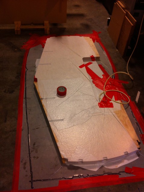
I did this by bagging it to the very flat and crack-free floor of my shop.  After some initial challenges getting a good seal, it worked quite well.

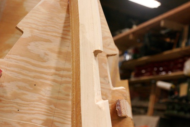
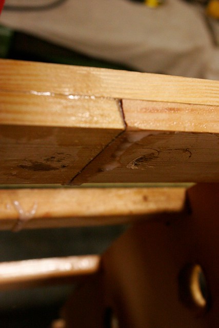
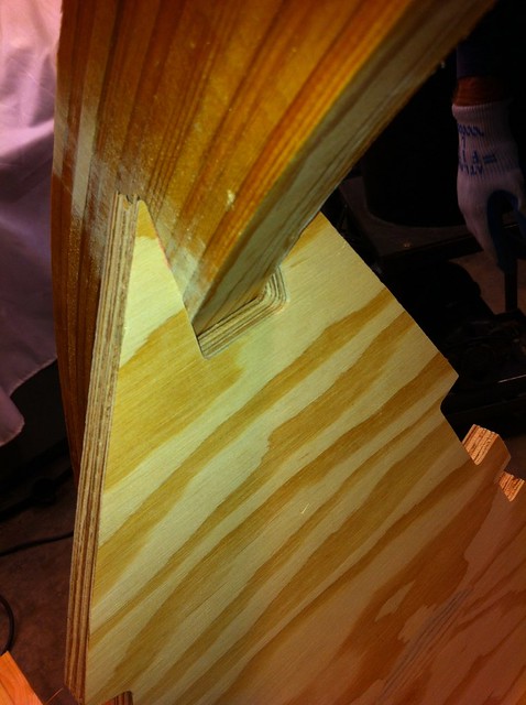
Unfortunately, however, I screwed it up completely.  No, dear reader, it wasn’t a bad layup.  The three layers were bonded together impeccably.  Instead, I aligned them incorrectly.  The three layers are not identical.  This is because the transom is tilted backwards on the hull, and so to develop a straight line through the layers you want the notches and motor well opening staggered.  This is hard to explain without a photo, and I don’t have a photo, but suffice it to say I lined them up incorrectly.

This rendered $300 worth of marine ply useless.  Sigh…  I guess this is one of those eggs you break making an omelet?

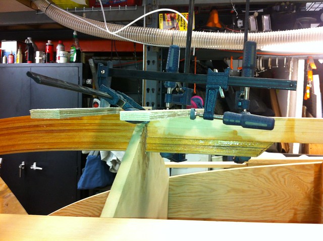
Anyway, after mentioning this to Timm he suggested that I’d really be better off just laminating the first two layers together to start with, and then adding the third after trimming the side stringers and chine logs flush with the ends of the portions of the transom in which they seat.  I guess that’s a bit of a silver lining, because in retrospect it made things a lot simpler.

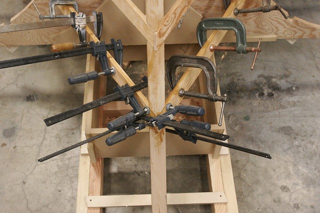
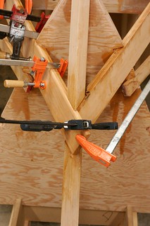
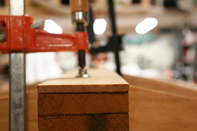
The vacuum bagging had been a bit of a pain, and I now had a 75 pound object that was exactly the shape of the thing I wanted to clamp, so for the 2nd go round I opted to forgo the bagging and just use weights.  After rounding up most of the heavy things from around the shop and stacking them on the bad transom on top of the good one, I let it cure overnight.  Of course, having foregone the bagging, the lamination didn’t go perfectly.  There was a spot in the lower corner of the port side that didn’t get bonded very well.  I was able to inject a bunch of epoxy in there though and get it pretty fully bonded with clamps after mounting it to the hull.  I have no concerns about its integrity.

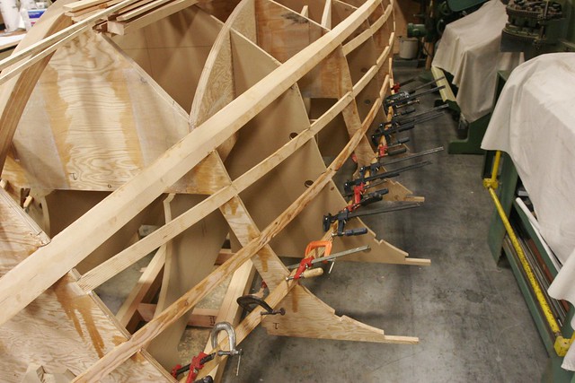
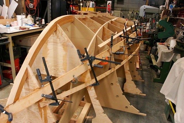
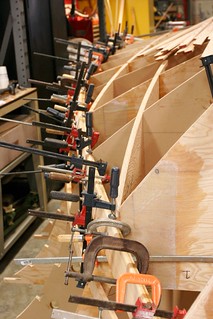
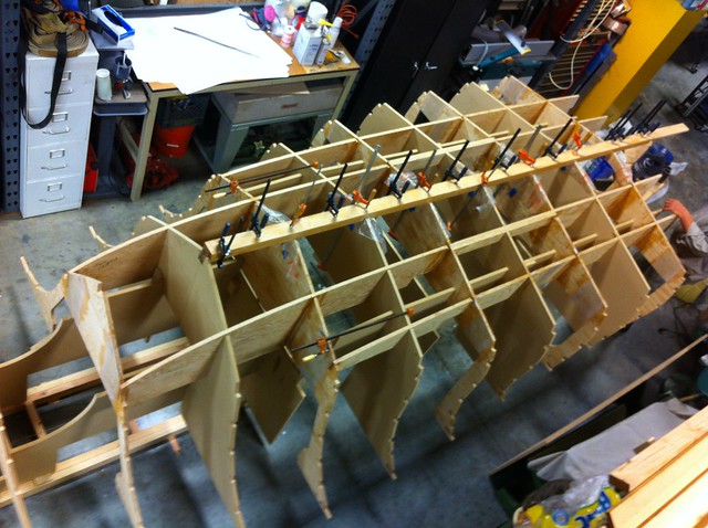
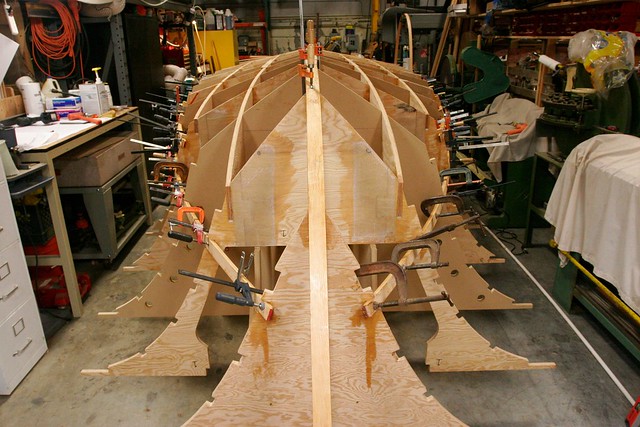
Here it is, all bonded up to the stern of the boat.  A careful observer will note that this is actually from a bit later in the process, but I don’t have a picture just after mounting it.

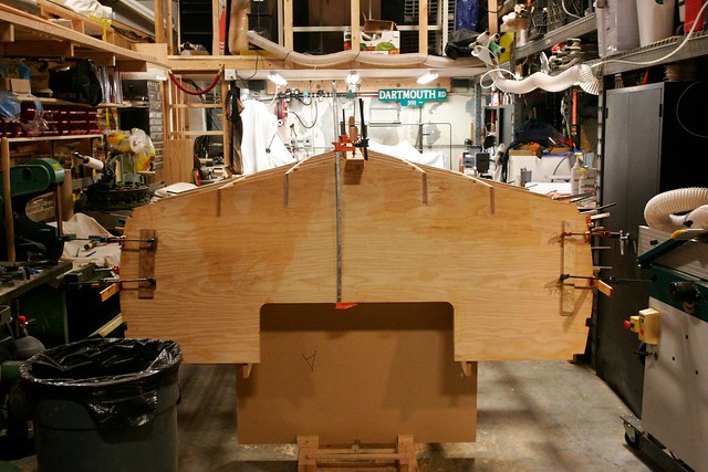
Getting it bonded on was relatively straightforward, though I did have to cut away a bit more of the strongback to make it all fit.  This was one of those cases I mentioned where I was comfortable enough that I was doing the right thing that I didn’t bother checking with Timm.  My bet is that it’s a function of the fact that I’m using Doug Fir plywood whereas he designed for Okoume.  Okoume is a little nicer to work with and is considerably lighter, but Doug Fir is stronger and much cheaper.  I’m unemployed.  I like cheap.

-Ben

PS – I’m pretty sure the statute of limitations on stealing street signs is less than 20 years, but if you live on Dartmouth Rd. in a Bay Area municipality I won’t name, please forgive a youthful act of indiscretion by an elated high school senior.

Committed

Up to now, with the exception of laminating the stem, there’s been a lot of CNC cutting and a lot of dry assembly.  But nothing really has been glued up and made permanent in a really-hard-to-undo kinda way.

Having surmounted the strongback issue, we’ve now positioned all the frames over the stringers and the next step is to bond them in place so it all becomes a single, rigid assembly.  Once this is done, there’s no going back, and precision here is critical for creating a foundation for a symmetrical, plumb and sound boat.

The frames were all marked with a waterline and centerline during the CNC phase.  The centerlines were aligned over a taught string positioned along the middle of the strongback.  That was easy.  Aligning the waterlines was harder.  In the end we clamped some small, straight boards along each waterline so that they stuck out to the side.  We could then sight along the boards and rest levels on them to get everything lined up and plumb.

Once I had triple checked everything, I bonded it all in place using cabosil-thickened epoxy to create 3/8″ radius fillets on all four sides of each vertical intersection.  (Note that you don’t bond the MDF pieces to the plywood since they’re temporary…)

In the above image, you can see that I left the fillets a bit short of the bottom of the boat (which is the top of the board).  That’s because the frames and stringers will all get bonded to the hull skin when applied, and I want to have a clean intersection of the radius on the vertical joints and the hull joints.  That’ll be easier if I come back and finish the frame-stringer fillets once the hull is on and turned.


-Ben