Category Archives: Framing

Forward Sheer Clamps

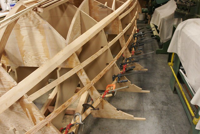
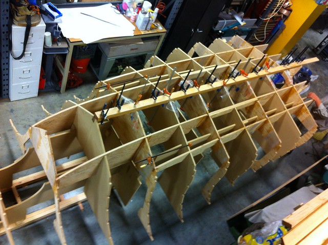
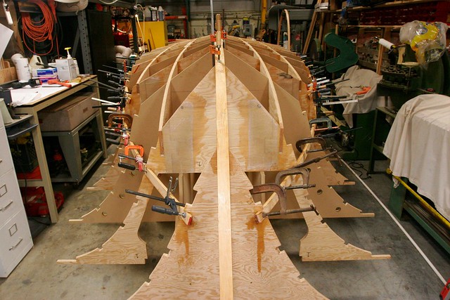
The last of the longitudinal members are now installed!  These are the forward sheer clamps, and they define the line at the outside of the top of the hull in the forward part of the boat.  As the Kitty Hawk 18 is a Carolina-style hull, it has a broken sheer, and a very flared bow.  The sheer line on a boat is – simply put – the line that the top of the hull makes when the boat is viewed from the side.  “Broken sheer” means that that there is a sharply divided sheer line on this hull.  In the aft sections, the sheer line is lower.  In the forward sections it’s higher.  And there is pronounced transition between these sections.  It’s also the case that the forward sheer on this boat flares widely relative to the aft.

Because the hull essentially “ends” at the sheer line, you need a stout member similar to the chine log which anchors the side of the hull and provides an attachment point for the topsides of the boat.  This is called a sheer clamp.  The aft sheer clamps went in with the side stringers and were pretty simple.  I didn’t bother discussing that.  The forward ones are trickier because of the complex curves.

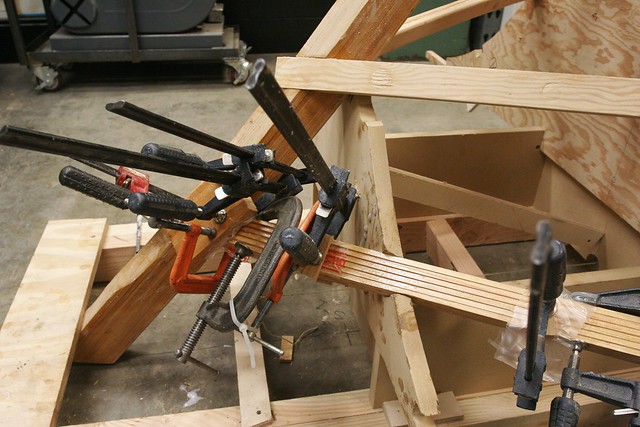
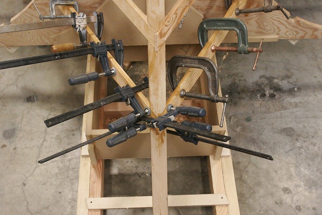
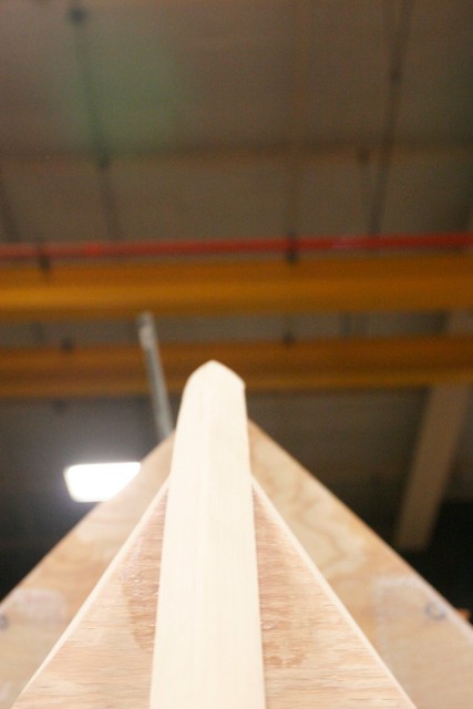
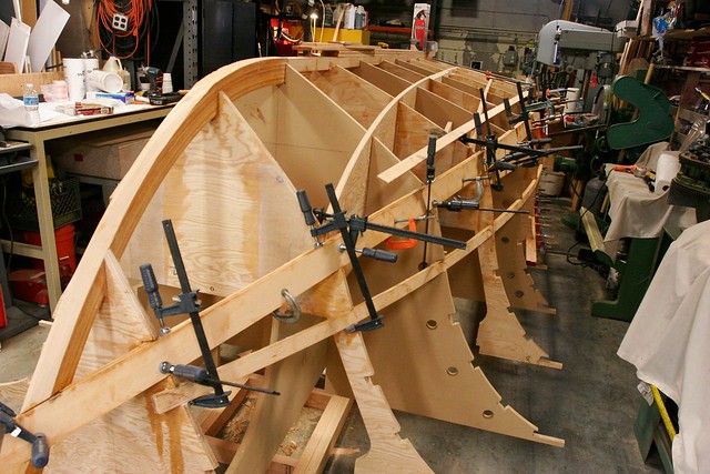
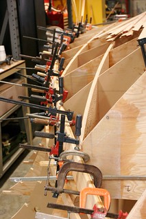
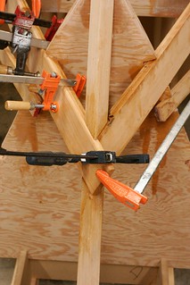
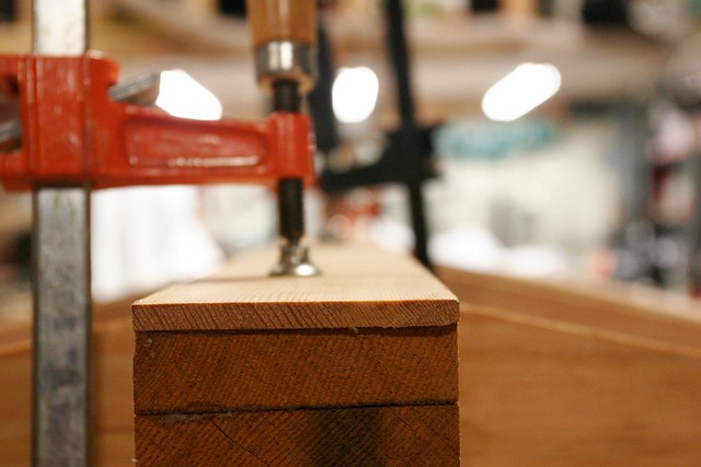
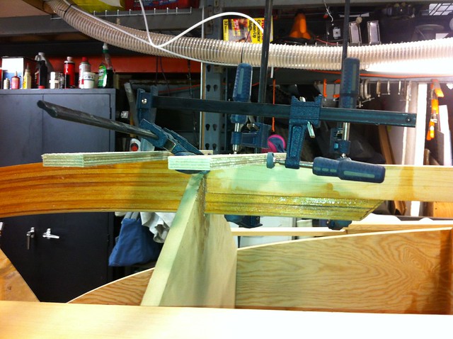
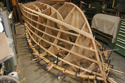
We decided to laminate them from eight strips of 1″ tall x 3/8″ wide doug fir. They didn’t need too many clamps – relatively speaking – so we were able to lay them both up the same day.  Here they are after being installed.

_MG_3327


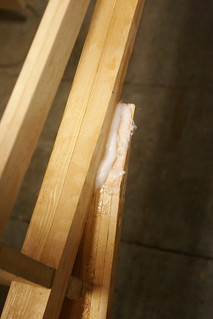
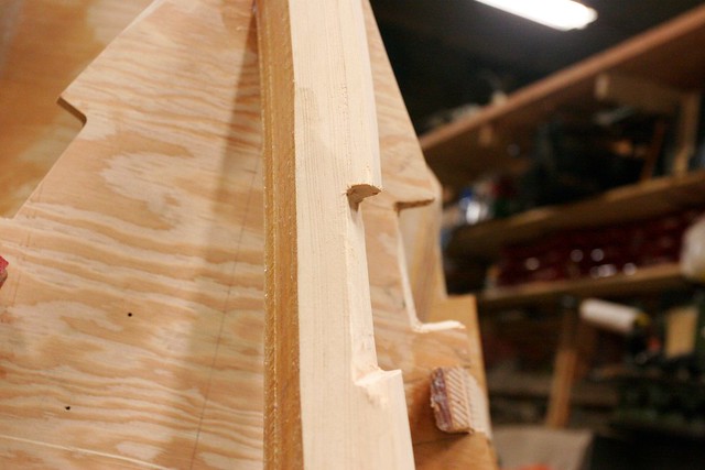
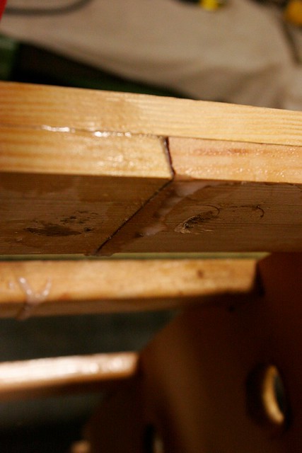
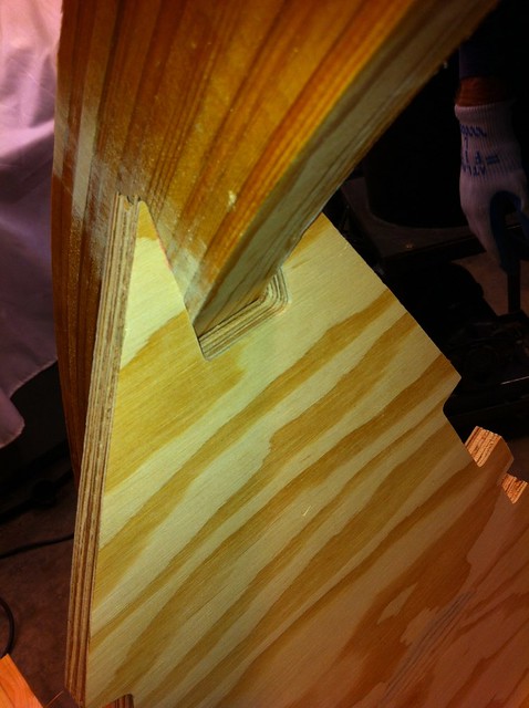
The intersection of the forward sheer clamp and the aft one is complicated.  Here’s the junction just after the clamps came off.  The outer sections of the forward one will get shaved away during the fairing process to produce a smooth junction.

_MG_3333

That’s it for the framing members!  Well almost, we still have to put on the third layer of the transom, but that’s pretty trivial.  The hard work of laminating these longitudinal members into position is done.  Next up: Fairing.
Stay tuned.
-Ben

Tough Stringers

First off, I apologize for the delay in providing another update.  The Florida trip got me off my usual routine. And now, on to the update…

The last of the stringers – the topmost in the bow – is tough.  It bends a lot in two different directions, both vertically and horizontally.  I tried bending a pair of 3/8″ strips in there and they broke.  Too much “hard way” bending.  So we had to do something else.  After mulling a couple of options, what we came up with was to stack six 3/8″x 3/4″ strips vertically rather than two 1-1/2″ x 3/4″ strips horizontally.  From a bending perspective, this worked great.  From an assembly perspective – total nightmare.

Anyway, we first milled a bunch of strips:

And then we laminated the starboard stringer.  Realistically this is where we made our first “ugly” error in the boat.  The strips slipped on us during clamping and we couldn’t get the parts lined back up, so we decided to live with it.  The ugliness will be completely buried later and invisible, but it’s annoying. Here’s a photo of it under clamp.  In the right hand edge of the picture, you can see that it looks more or less like a composite, rectangular board.  Toward the left side, it’s slipped so it’s more of a stair-step.

On the upside, we learned some lessons on this first one, and by the time we got to the port side we did a much better job.  Next up, we have to install the last of the longitudinal members – the forward sheer clamps – and then fair all of the framing.

Exciting stuff!

-Ben

The stringer slog

Installing side stringers is a patience-trying endeavor.  There are a lot of them, and due to the nature of this boat, each one takes a fair bit of time to set up and clamp.  Then you wait overnight and do it all over again.  In total, there are 10 stringers to put in, and a lot of them “whole day” projects, not because it takes all day, but because of the number of clamps required and the delicate nature of the operation.  Once they’re on there, I’m loathe to bang around on the hull lest I unseat something.  So you end up knocking off early those days, which feels pretty inefficient.

With the exception of the very top stringer (which is the bottom one on an inverted hull) they go in pretty easily.  I won’t bother you with long-winded descriptions, but here are some photos to give you a sense for what’s involved.

My father is fond of the adage “Patience is a virtue.”  I’m ready to be done with stringers, but this is a critical step and can’t be rushed.  These set the foundation for the hull skin, and it’s a lot easier to get it right now than to fix it later during the fairing process.

-Ben

Chine Logs

I’ll start with a nod to my father’s suggestion, buried somewhere down in the comments, that I be a bit better about explaining arcane boat building terminology when I employ it.  A boat such as this one has “hard chines.”  The chine is the intersection between the sides of the boat, and the bottom of the boat.  In the forward (front) areas this is a barely perceptible transition, but as we move aft (back) it quickly becomes a sharp angle.  That sharp angle is what’s implied by the term “hard chine.”

When we plank (skin) the hull we will use one set of planks for the sides and one for the bottom.  These intersect at the chine, and they need a fairly stout piece of framing behind the intersection to support them and bind them together.  These are known – presumably for reasons dating back to when they were comprised of actual logs of an appropriate shape – as “chine logs.”

The chine log on the KH18 starts at the transom and runs all the way forward, ultimately intersecting with the stem.  It’s for this reason that the keel and stem were just installed in the boat – I had to mate the chine logs to the stem, so it had to be there first.

Step 1: Shape the stem.  When the stem was installed it was  a curved block of wood.  The bow of a boat is not, however, a a flat chunk of wood.  It’s nicely pointed to break water.  To achieve that angle, I took a block plane and a spokeshave and trimmed off the edges until the desired angle was achieved.  Here’s an “in progress” shot of that:

Once the angle was right, I had to notch out pockets for the chine logs to sit in.  This was done with a pull saw and a very sharp chisel.  Here you can see the starboard side pocket, with the corresponding notches in the plywood frames in the background:

The chine logs are 1″ x 3″ total, comprised of two strips of 1/2″ x 3″.  Here’s the starboard one after being laid on and clamped in position:


And here’s the port side, installed after the starboard had fully cured, the forward end trimmed and a port side notch cut.


Later, these will have to be shaped with a block plane to achieve the correct angle and size, but more on that later.

I should note at this point that for efficient use of material, in many cases I’m creating composite members not just for thickness, but also for length.  The chine logs and most of the stringers are comprised of sections.  Here’s a shot of one of the joints:

This has only a minor effect on the strength of the member.  The butt joint between the two sides is completely filled with thickened epoxy, which is as strong or stronger than the wood surrounding it.

Keel laying

Traditionally, I guess the first thing you did when you built a boat was to lay the keel.  Or maybe that’s just with ships too big to be built upside down.  I don’t know, but I do know that I did a lot of work before I got to the point it was time to assemble the keel.  But that time has come!

The first step is to laminate the aft portion of the keel.  This is done in place, on the frames, so that it fits the contours perfectly.  But you have to be careful not to actually bond it to the frames because you have to be able to remove it after it’s bonded so you can shape it to mate with the stem.

Here’s the keel being laid up.  If you look closely you can see that there’s a piece of plastic between the keel and the frames at each station.

Here’s a shot from the aft end of the keel…

Don’t stress about those cracks in the bottom member.  The keel overhangs the transom by a fair bit at this point and the cracks only run an inch or two forward.  Besides, that piece is now bonded to the one above it, which will hold the cracks together.  This is one of the many reasons a composite board is stronger than a single board of the same dimensions.

Once the keel cured, it came off the boat and got fitted up with the stem.  That required that the forward end of the keel be tapered in on both sides, and that a notch be cut from the stem to create a longer joint.  These were then clamped and bonded in place on the boat.  Here’s a shot of the whole kit ‘n’ kaboodle being clamped on the boat.  The Stem is the part on the left, including the protrusion that sticks aft of the MDF frame by a bit before tapering down.  The keel is the lighter-colored piece that’s resting on top of the protruding portion of the stem.

Those two small pieces of plywood on the tops of the two parts were nailed there temporarily to give a purchase point for applying clamping pressure to pull the two together.  then it was clamped in a couple of other places vertically along the 10-or-so inch long joint.

The keel is 3″ wide and 1-1/2″ tall.  The stem is 1-1/2″ wide and 3″ tall.  That’s why the keel needed to be tapered in the forward end to fit.  That was an amusing operation for which I don’t have a photo.  Basically we cut wide of the mark on the bandsaw and then snuck up on the line on each side using a 24″ pedestal disc sander.

The keel is done!  Long live the keel!

-Ben

Longitude!

Or, more accurately, “longitudinal.”  We’ve got the plywood framing all in place at this point and it’s time to start laying the lengthwise timbers.

“Longitude” as a posting title, however, gives me a chance to plug an exceptional book of the same title by Dava Sobel. You’ll never take your watch for granted again after you understand the scope of the human effort that went into developing a method for keeping time that could remain accurate while aboard a vessel rocking on the ocean.  Pendulums don’t like that much…

But I digress.

Whereas thus far, with the exception of the stem, we’ve been working exclusively with sheet lumber – plywood and MDF – we’re about to start working with more traditional boatbuilding materials.  We’ll be constructing longitudinal members by laminating together strips of V.G. Doug Fir as necessary to make the bends required by the design.  We’re starting with the bottom-most side stringers, which you can see clamped up in the following photo:

The required final dimension for these stringers is 3/4″ wide by 1-1/2″ tall.  To get that, we’ve ripped 8/4 planks into a set of 3/8″ strips, and then laminated two thicknesses of strips together on the frame to build each stringer.  This composite glue-lam construction is required because the bends are too great to complete with a single piece of wood that’s 3/4″ x 1-1/2″, but there’s an added benefit that a well-laminated composite member is stronger than a single member of the same dimensions.

One thing we’re beginning to discover at this stage is that the number of clamps you have is often a binding constraint in how much work you can do in a day.  I bought 40 clamps at the beginning of this project.  That was nowhere near enough to laminate these members.  My friend and neighbor Wolfgang has generously loaned me about 40 more and with that I can generally do two simple stringers at a time, or one more complicated one.  Since each layup needs to cure overnight, this often means we do about 3-5 hours of work and then have to quit because we can’t go any further until the clamps come off.

One other point to note here…  I glossed over a step that’s actually quite critical and takes time to do well.  As you can see, the stringers are not generally perpendicular to the frames where they cross them.  That means that they’re not parallel to the notches in the plywood that were cut for them by the router.  I don’t have a good photo to demonstrate this for a stringer, but you’ll get the idea from this photo of the stem where it crosses the forwardmost frame:

The stem only touches the frame right at the front.

With all of these frames, the “controlling dimension” is the back of the frame.  If anything in front of that prevents a part from resting properly on the back of the frame, it has to be cut away, and cut away in a fashion that creates a good gluing surface along the entire length of the bond.  My friend Shawn Hibmacronan came to the rescue here with a loan of an awesome 3/8-Inch Makita Belt Sander.  This thing rocks.  I just went into each slot with the sander and ground away enough material for a perfect fit.  I now own one.  This thing will save me countless hours.

Anyway, before I could laminate these stringers in I had to go and do all that shaping.  If you look closely in the photo of the layup, you can see that some of the other notches are already shaped.

-Ben

PS – It may look like I’ve installed the stem at this point, but I haven’t.  It’s just resting there right now.